Continuing work part 3
It was another productive weekend in the garage/shop. I’ve been needing to get the valve work finished on the Fairbanks-Morse motor so I decided to tackle that. I wasn’t comfortable with the bronze valve guide expansion rate in the cast iron when heating while running. We used Bronze valve guides in the cast iron heads when I worked for Harley, but replacement heads are easier to find for old Harleys than they are for this engine. So, I made a new set of guides in cast iron, to go in the cast iron head, and everything should expand approximately the same and nothing should crack. I won’t go into the making of the guides as the machining is the same as the bronze guides. After the guide is cut then the head needs to go on the mill table and be prepared for machining the previous guide hole to accept the new guide.

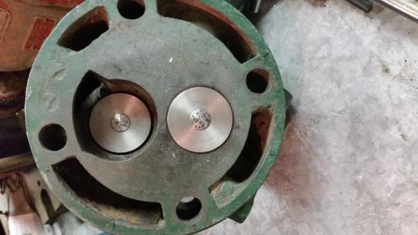
The head is locked to the table and I have chucked a piece of material in the spindle that is the same size as the old valve guide bore. This is my home-brew way of aligning the work piece to the mill machine, and it works good enough for this kind of work. I keep adjusting the mill table until the chucked material moves freely in whatever I am trying to align.

Once it’s a free slip vertically in the hole, I consider it aligned and its on to the next step. Make sure you use a straight piece of material in the spindle, otherwise your hole will still be off. Next I removed the locating piece and chucked up a 21/32″ HSS drill bit and started roughing the bore in.

I always take it easy when starting a hole in soft material like cast iron with a large bit like this. It’s too easy for one of the drill bit flutes to bite and ‘grab’ the work, pulling the drill bit off center and throwing off the bore. It goes against proper machine work, but I kick the spindle speed up really high and then lightly ‘peck’ at the hole a few times to get the bore started and just below the surface. Then I slow the bit down to proper cutting speed and cut at normal feeds/speed. In the above pic the bore looks centered and it’s cutting good.

Done with the drilling portion and there is a nice even amount of material still left around the hole. Hit it pretty dead on center and I’m happy. Now I need to ream it to final size. Since the reamers I have are of different types, chucking and hand reamers, I sometimes have to get creative about how to ream a hole. I would prefer to have all chucking reamers so I can just drop the drill bit out, chuck up the reamer and keep everything concentric, but my budget isn’t going to allow that. Lol

So here is how I keep my hand reamers in line and concentric. I have a brass center I turned up and mount it in a collet, which sets in the pilot hole in the back of the reamer. I use small amounts of manual down feed to keep the center ‘locked’ into the pilot and then turn the reamer with a wrench till it feels free in it’s rotation. Apply a little more down feed and repeat. It’s slow but it works.

You also get a visual indicator when the reamer is through the material. That concludes the work needed on the head until it’s time to insert the new guide. The next step is to take measurements from the hole that you just made in the head, and a measurement from the outside diameter of the guide that will go in the freshly made hole. The reamer finishes a hole to 0.6875″ and the outside of my guide was at 0.710″. I turned down the outside of the guide for a proper interference fit of 0.0015″ larger than the hole. I then put a chamfer on one outside edge of the guide, put a tiny bit of high pressure lube ont it and checked the fit.

Well, that looks about right. Feels about right. Astute readers will see a line cut toward the top of the guide. I part most of the way through the guide at total length plus about 1/8″, it comes in handy during the install of the guide. Time to smack it a few times with the hammer and see how it seats.

Almost fully inserted to depth, you can see how much is left thanks to the groove that is cut. Now the lube isn’t on the portion that is driving into the head and there is more resistance to the guide going in the hole. If I got everything right, just about the time it gets to the right depth…..

Perfect. The valve seated to depth and the last tap with the hammer caused the groove to fracture, leaving about 1/8″ standing proud over the hole. Now the head goes back over to the mill table.

A nice pic of the guide and you can see the parting line where the top snapped off. I like to finish this off in the mill with a cutter to bring the guide flush with the old castings, making everything look nice and neat.

That takes care of the outside of the guide, the inside is already done, and we are finished with using machines to do the work. From here on out, it’s all by hand and feel just like I was taught.

A quick run of the reamer through the guide to make sure any burrs or debris is clear of the hole and I can slide the new valves into the head. The valves look and feel good, I get a satisfying whump when they drop into place, the sound that says they will take just a little lapping to seal up good and tight. The sound you dont want to hear is a tinny ring when you drop the valve in the hole. That ringing means some part of the valve isn’t seated against the head. Final pics before lapping the valves.

